

How To Tell If Washing Machine Control Board Is Bad
Introduction
After ~10yrs the buttons weren't working right on our WBVH5300K0WW GE front end load washing automobile. Eventually pressing harder would trigger the display over buttons to the left of the button beingness pressed. I volition explain how you can replace the tactile switches instead of the entire control lath. Note: To practise this you should be comfortable with soldering and de-soldering parts on a circuit lath and have the proper equipment (soldering iron, solder sucker, ohm meter).
-
-
Read through the entire guide. and have a look at your control console and switches in case they are different.
-
I constitute the right size switches at digikey.com part# 2449-CR1102H4.3F160CT-ND. Part# 2449-CR1102H4.3F260CT-ND is the same size just requires 260g of force to actuate the switch instead of 160g. Note: I can't seem to change the link for the second part # so if ordering the 260g strength switch change 160 to 260 on the part #.
-
My washing machine had 9 switches so I ordered 10 (of both switches). I installed the 160g force switches every bit they took nearly the aforementioned force to activate equally the original switches.
-
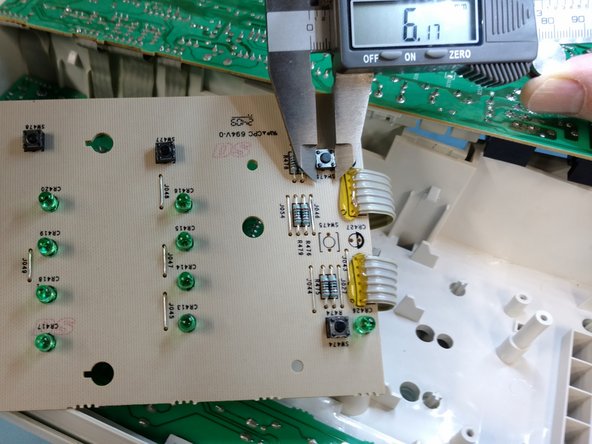
My circuit boards take plenty of space around the switches. Whatever momentary tactile switch that is roughly 6.2mm on a side with the tiptop of the push virtually 4.4mm to a higher place the board with only 2 pins with a pivot spacing of 5-5.08mm should work.
-
-
-
Slide out the soap drawer and gently push downwardly on the tab while sliding information technology out.
-
Note: There volition probably be water in the soap drawer so empty it and set information technology to the side.
-
-
-
Remove the screw on the lesser left side that sits backside the soap drawer.
-
Put the spiral with the drawer as many of the screws are different sizes.
-
Annotation: I found information technology helpful to utilise blueish painters tape and tape the screws in groups to the parts being removed or to the washing automobile top near where they screw in.
-
-
-
The picture is looking downwards on the washing machine from to a higher place. Remove the three screws holding the curved plastic piece on.
-
Gently pry the front meridian back and information technology should pop off.
-
Prepare information technology bated with the three screws (preferably taped to the plastic).
-
-
-
Unplug the washing machine.
-
Remove the three screws at the back that hold the top on. Note: At that place are extra holes on either side of the exterior screws. You may want to mark the hole that has the screw with a pencil or piece of tape.
-
Slide the height towards the rear nigh 1/ii-1"
-
Raise the forepart edge of the peak a few inches and slide the height back another three-4". You should be able to find a position where the top lies flat on the washer.
-
-
-
Remove the iv screws that secure the control panel.
-
With your hands on either side of the top lip of the command panel gently pull upwardly and forwards until the control panel moves forward.
-
Pull gently on the bottom right of the command panel to release the clips holding the control panel in place.
-
-
-
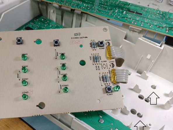
The two arrows on the correct show the clips that were holding the correct side in place.
-
At this indicate yous could use a ohm meter to examination some of the switches. The resistance when the switch is pressed should exist a few ohms or less.
-
My switches measured betwixt 200 ohms and 2K ohms when pressed and were likely the problem.
-
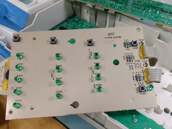
The picture with the circles show where a few of the switches are. Again, make sure the washing machine is unplugged. Put an ohm meter across the ii large solder blobs in the circle and press the button. You may need someone to concord the control panel while yous do this.
-
If this is likewise awkward you can remove the control panel and then exam the switches (come across the next step).
-
My meter showed about 7K ohms when non pressed. Note: The 7K ohms is from resistors on the board, not the switch. When the switch is pressed the resistance betwixt the solder blobs should be a few ohms or less. If the resistance is much higher the switch is probably bad and should be replaced.
-
-
-
Assuming your switches tested bad it'southward time to remove the control panel.
-
I recommend taking a few pictures of the connecters before proceeding. I believe each of my connectors would only fit in one place simply yours could be different.
-
Each connexion has a tab that needs to be pressed when removing the connector.
-
The arrows bespeak to the few tabs visible in this picture.
-
-
-
Note: I don't know how static sensitive the excursion boards are so if the humidity is quite low (pregnant static can build up and you may zap something by touching information technology) try grounding yourself earlier you touch the circuit board. If y'all get upwardly and walk around, basis yourself before touching the boards again.
-
If you accept an apparatus with a metal body and a 3 pronged electrical cord (a microwave etc) you lot can touch the metal instance to ground yourself. Notation: Yous Do Non need to turn on the apparatus, but have information technology plugged in.
-
The switches are on the ii lower boards and then remove the top lath by removing the five screws (commencement picture show) property information technology in place.
-
The 2nd picture shows where you should put your fingers to gently pull the plastic bar upwardly over the standoffs (where the screws adhere).
-
One time the plastic bar is complimentary pull the board towards y'all a bit. Detect how the dorsum of the board fits between plastic tabs at the back. This will be important when re-assembling the boards.
-
You tin gently lay the summit board over the back leaving all the ribbon cables attached (third picture show).
-
-
-
Remove the four screws securing the right excursion board.
-
You lot can gently elevator and flip the lath to the left (every bit shown in the second picture). You can see the five switches on the front of the board.
-
It may be helpful to use a pen and draw a circle around each switch on the dorsum (green side) of the board. This may relieve time when de-soldering the switches. Notation: If any of your switches tested bad I'd modify them all. At 20 cents each information technology's not worth opening the washing machine again subsequently.
-
If you lot oasis't measured the switches however now is a good time. The third picture show shows how I used a digital caliper to mensurate the switch so I knew what to order.
-
-
-
Annotation: When I was replacing the switches the scent from the board/solder was awful. I'd recommend doing this outside with a fan to gently blow the fumes away.
-
Once more, I assume y'all know how to solder & de-solder the switches. I used a solder sucker to suck the solder of all the switch connections.
-
Note: I don't have a moving picture for de-soldering considering at the time I wasn't thinking about writing this guide.
-
Try removing and replacing only one switch at first. This way you can compare the physical size, elevation, pivot spacing, and actuator force betwixt the new and onetime switch.
-
Once as much of the solder as possible is removed from the pins on the start switch I used a small flathead screwdriver to button on the pins to break them free from the board. If that doesn't work employ the screw commuter to gently pry the switch out from the front while heating the solder from the bottom.
-
-
-
Once the old switch is removed cut off one of the new switches (beginning picture) and compare the two switches. Leave plenty pivot length. Y'all tin can always cut it shorter after soldering. Brand sure it fits in the hole and that the button is roughly the same height every bit the old switch.
-
Annotation: The holes in my board are much larger than needed, fifty-fifty for the old switches. I found information technology helped to bend the pins to keep the switch from falling out of the board when I flip the board over to solder it.
-
Put the new switch in and concord it in place with i hand. Use your other hand to bend the leads in opposite directions. Bend it along the broad side of the rectangular leg (the easy way). The 2d movie shows the aptitude legs after ane switch fell out earlier I could solder it.
-
Solder one of the switch legs to the board. And then flip the board over and come across if the switch is lined up with the switch outline drawn on the front end of the board. If information technology doesn't look centered, heat the solder and slide the switch a bit until centered.
-
Once the switch is centered put the board in place and hold it down while pressing the button on the front panel for the switch you just replaced. If yous hear the switch click when the push button is pressed then the switch is in the correct place. If it clicked solder the remaining pivot to the lath.
-
If it doesn't click you probably need to move the switch a bit to line up with the plunger for that switch (arrows in third picture). Try looking at the plunger and the switch equally y'all put the board in place to get an idea which way to movement the switch. Re-heat the solder and slide the switch as needed and solder the remaining pin.
-
-
-
Once all the switches on the board take been replaced cut off excess lead length from the new switches.
-
Reinstall the board and spiral it downwards.
-
Press each push button i more than time and heed for the click.
-
-
-
Unscrew the left excursion lath. Note: Mine had spots for 7 screws but merely six were installed. Might non mater only I took a picture and fabricated sure to put the screws back in the same holes.
-
The second picture shows 2 plastic tabs that take to exist pressed towards each other to release the board. The tabs are far enough apart that I could press one at a time while lifting that side of the board.
-
Once the left board is loose alter all the switches and bank check the alignment (listen for the click, same equally the last board).
-
Trim the backlog lead length.
-
In one case all switches piece of work spiral the board back downwards and listen for clicks ane last fourth dimension.
-
-
-
The three arrows testify where the rear border of the board has to get to exist held in place. The board should be between the two vertical ridges and the triangular tab on the top.
-
Slide the board with the plastic bar over the standoffs.
-
Screw the board down.
-
-
-
Reinstall all the wiring to the control panel and compare it to your picture to make sure information technology's correct.
-
Go in opposite society to put the residue of the washing machine back together.
-
Note: When I was done I plugged in the washing auto and all the buttons worked (and there was much rejoicing).
-
The adjacent mean solar day my wife tried to do a load of wash. She said it wasn't filling with h2o and sounded unlike and so she unplugged it.
-
Hours later, when I got domicile, I plugged it back in. Information technology knew it lost power without finishing the bicycle so information technology tried to bleed the water (no h2o to drain) and then unlocked the door.
-
I did a load of wash and it worked fine. Non sure if there was a problem or she was confused and unplugged it when it was working. Don't meet how irresolute switches would crusade information technology to act funny.
-
Either way it works fine now. We've done dozens of loads with out a problems.
-
Adept luck.
-


Conclusion
To reassemble your device, follow these instructions in reverse order.
Embed this guide
Choose a size and copy the lawmaking below to embed this guide as a small widget on your site / forum.
Preview

How To Tell If Washing Machine Control Board Is Bad,
Source: https://www.ifixit.com/Guide/Washing+Machine+Switch+Replacement+(fix+control+board)/137776
Posted by: foxpoldned1975.blogspot.com
0 Response to "How To Tell If Washing Machine Control Board Is Bad"
Post a Comment